

Use at your own risk !!!!
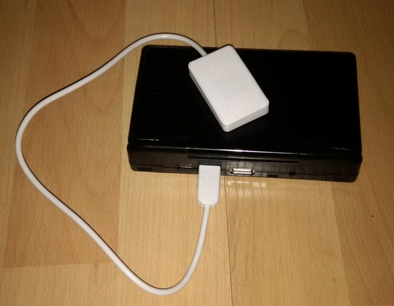
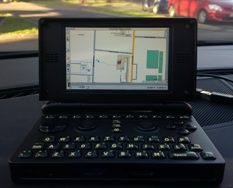
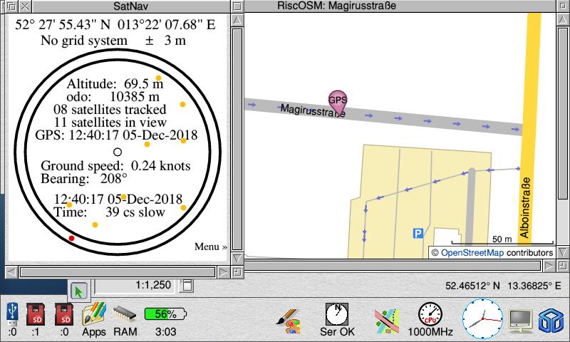
This is a short set of instructions for building a "GPS-Receiver" for the Pandora, bsed on the Adafruit-GPS-Breakout board.
Electrically, it is also possible to use and Adafruit GPS HAT, but there is no 3D template for pirnting out the housing.
I have not decsribed my internal variant on this page, as the efforts involved outweight the limited benefits, and an additional antenna is required anyway.
Up to now, I have only tested the GPS Receiver whilst running RISC OS on the Pandora.
1. EXT Connector for the Pandora
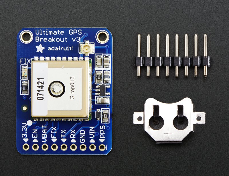
2. Adafruit Ultimate GPS Breakout
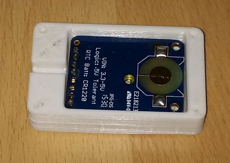
or
2. Adafruit Ultimate GPS HAT for Raspberry Pi
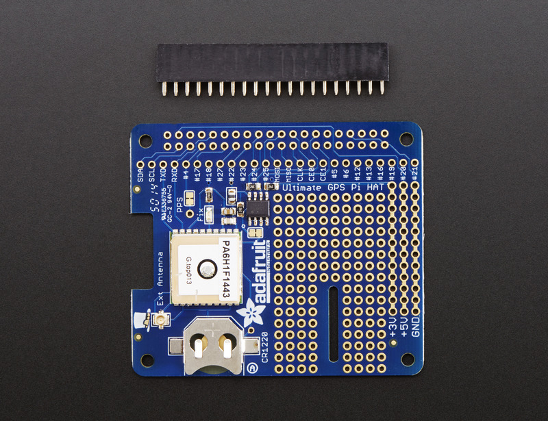
3. Three or four core cable, to the length required.
4. 3D Printed case for the EXT connector and GPS Breakout (this won't fit the GPS HAT).
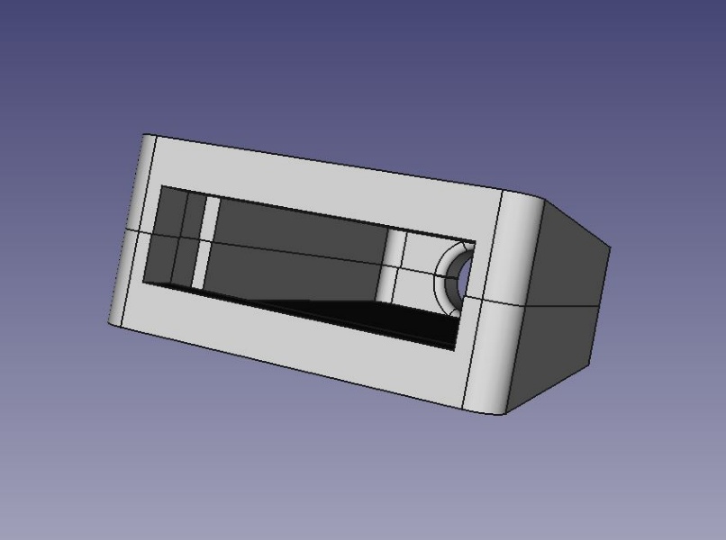
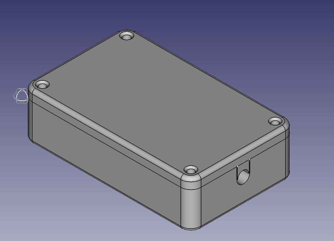
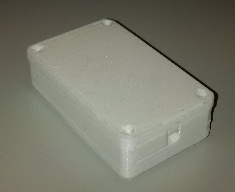
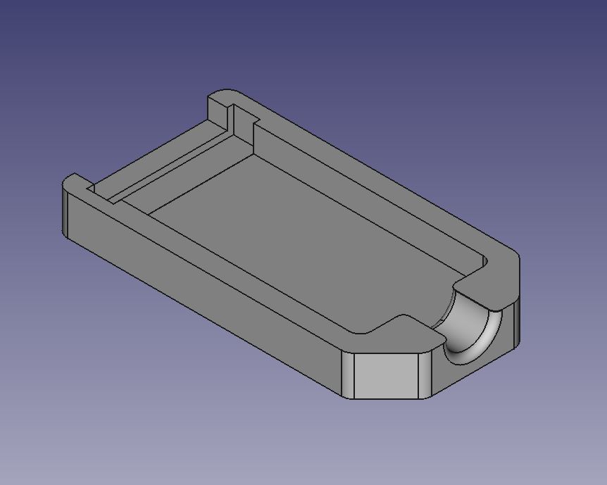
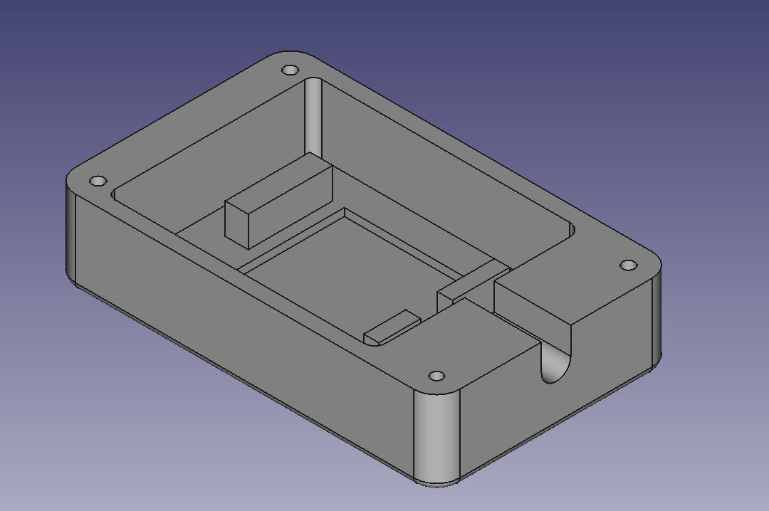
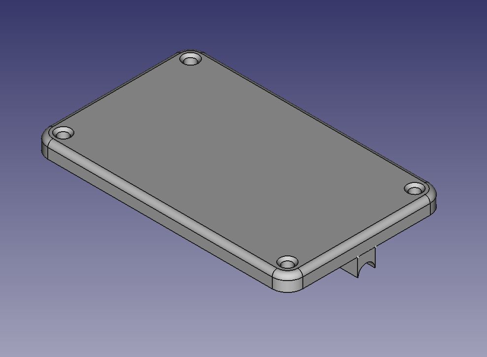
Download STL-Files.
1. "Helping Hand" A to help you hold the GPS board and the EXT connector
2. A small soldering iron with needle tip
3. Side cutters etc.
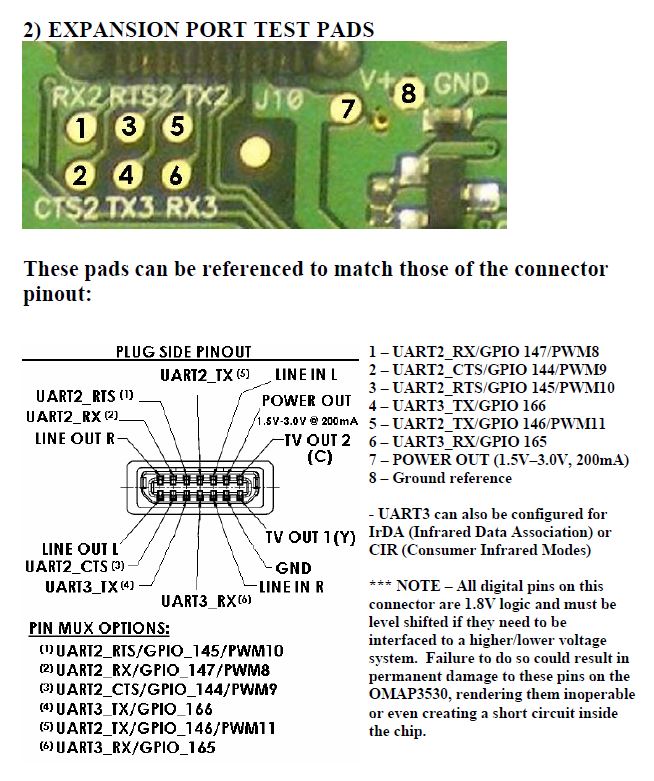
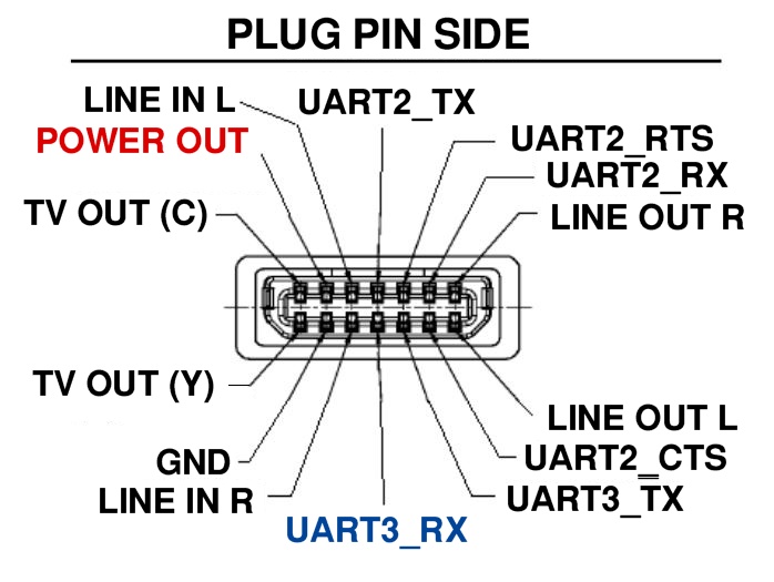
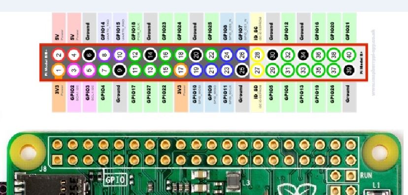
On the Pandora, using the four core cable, we need to connect the RX, 3V and GND to connect to the EXT connector. It's worth bringing over the TX too, while we're at it.
Then, solder the cable according to the following instructions:
Breakout ----------- Plug
GND ------------- GND
3V ------------- 3V
TX ------------- UART3_RX
optionally (I never try!)
RX ------------- UART3_TX
With the GPS HAT, connect them as follows:
GND ------------- GND
3V ------------- 3V
And, beware the difference:
RX ------------- UART3_RX
optionally (I never try!)
TX ------------- UART3_TX
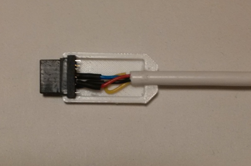
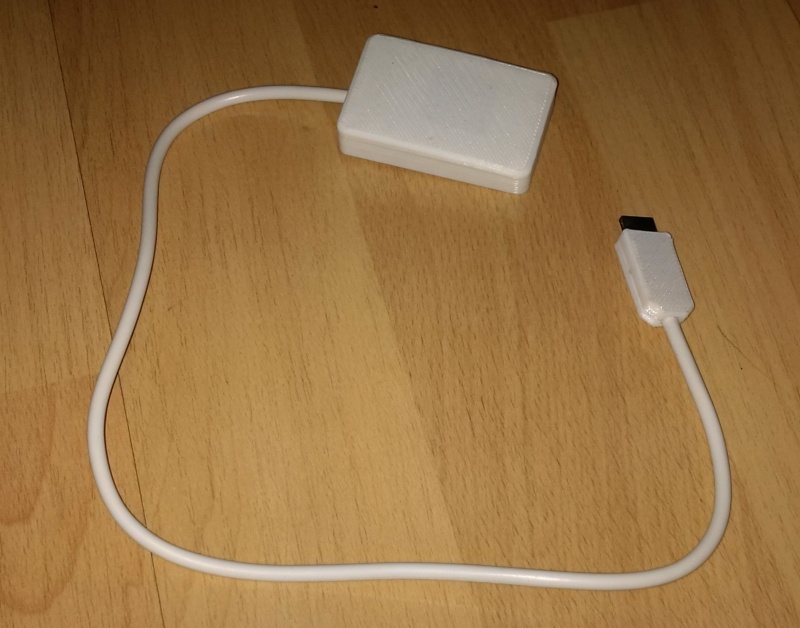
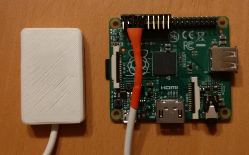
And we're done!
This is the first testing solution and ...the ready Pandora solution. Works comparable in my DIY PiTab.
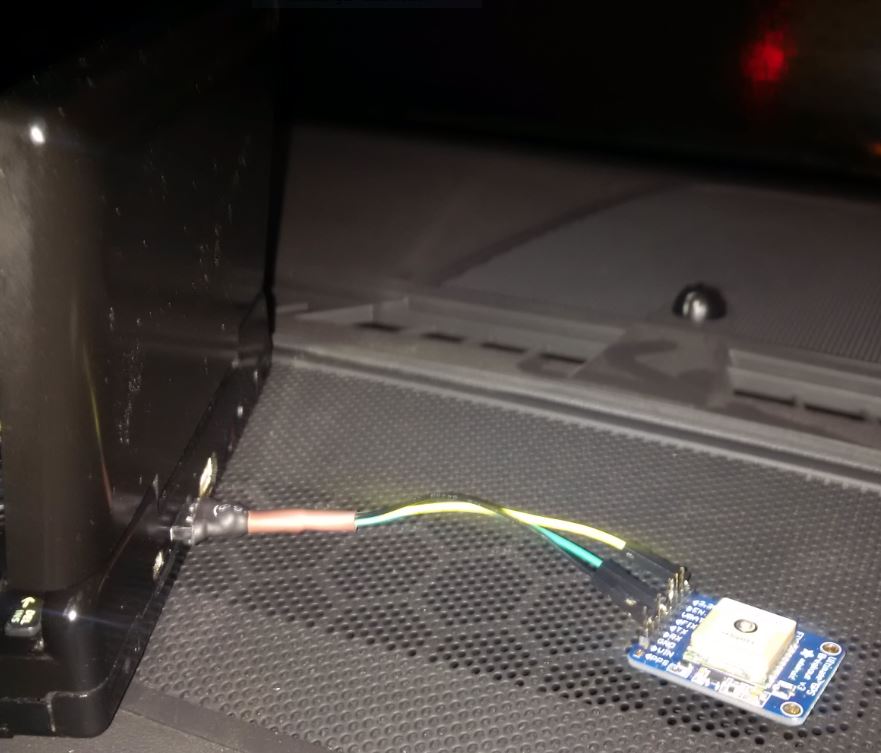
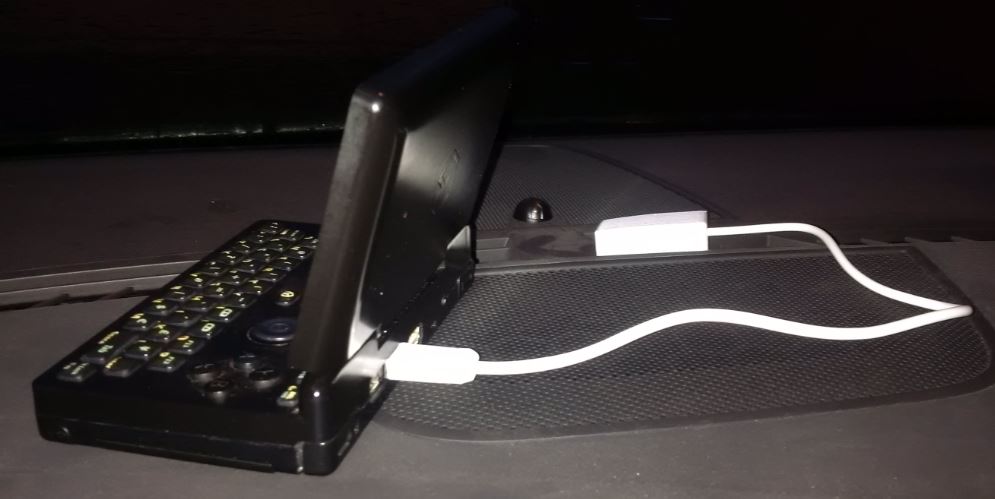
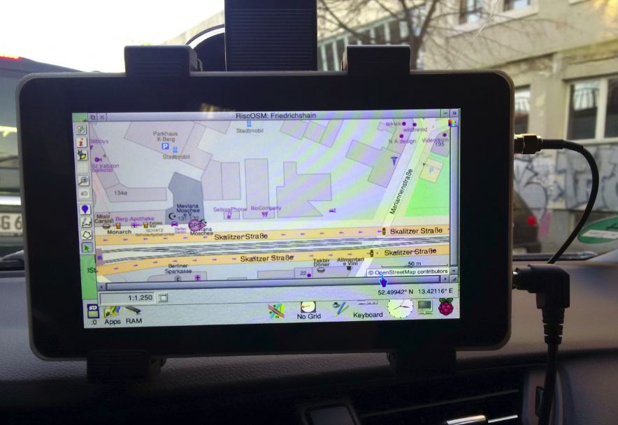
The GPS receiver now needs to be able to "see" the satellites, and we need to set up the software.
This works on my Dashboard (in cockpit behind the front window) without issue.
Adafruit has instructions and descriptions for using navid and gpsd.
If you wish, you can still connect an external GPS receiver.
Have fun and solder carefully!